Mapping
Network of Workstations versus SMP
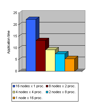
Figure 39 presents the analysis for the LU code from NAG, when running on a network of workstations or on an SMP. For this example, we have used unlimited resources (buses and links), 0 latency and bandwidth of 400MB/s and 700KB/s, for local and remote communications, respectively. The application execution time is clearly reduced from using 16 nodes of one processor to use 8 nodes of 2 processors each. The same percentage of reduction is not observed when reducing the number of nodes, but the execution time is still decreasing.
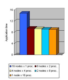
The same analysis for CG benchmark (from NAS suite) is presented in Figure 40. The reduction is not as significant as in the previous case, furthermore when using more SMP the time reduction is negligible.
Task to node mapping
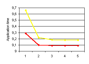
Depending on task to node mapping applications behave completely different, as local communication (in a node) are much faster than those communications using the network. Inter node communications require more resources and obtain worst bandwidth than local communications. Figure 41 and Table 4 ilustrate this example. Yellow line corresponds to a linear mapping and red line corresponds to an interleaved mapping. Both correspond to the CG application, simulated using 80 Mbytes/second bandwidth, 25 mseconds latency, 16 buses and half-duplex links. The number presented in the X-axis correspond to the number of half-duplex links per node. For this example, the best mapping is clear, the one providing the red line.
| Node | Yellow | Red |
|---|---|---|
| 1 | 1,2,3,4 | 1,3,5,7 |
| 2 | 5,6,7,8 | 2,4,6,8 |
| 3 | 9,10,11,12 | 9,11,13,15 |
| 4 | 13,14,15,16 | 10,12,14,16 |
Network conflicts
Injection mechanism
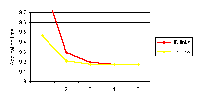
Figure 42 presents the analysis of the CG benchmark using the following configuration parameters: 4 SMP nodes, 4 processors each, 16 buses, 40 MBytes/s bandwidth and 25 mseconds latency. The variable in this analysis is the number of links. Yellow line represents full-duplex links and red one represents half-duplex. This example demonstrates the importance of full-duplex links when links are a scarce resouce.
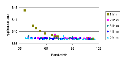
Analyzing the influence of number of links and communication bandwidth is another possible analysis. Figure 43 presents the results for the SP benchmark using different bandwidth values and different number of links. The SP corresponds to a 16 tasks example, and we map them to a 4x4 SMP. In this example, the number of available buses and the communication latency are also variables. Valid values for number of buses are form 1 to 16, and the range for latency is from 10 to 40 mseconds.
Contention
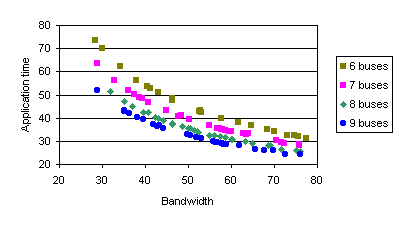
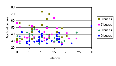
Figure 44 and Figure 45 present the analysis on the influence of number of buses when varying the the latency and the bandwidth. We have used the benchmark Exchange from PBM, running on 16 processors. The effect of modifying the bandwidth and the number of buses, has a high correlation to the application ellapsed time.
Heterogeneity
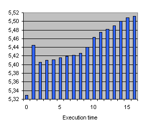
In this example we analyze the influence of running our application in an heterogenous network of SMP's. We select for this experiment the LU function from NAG library, running on 16 processors, over a 700KB/s badwidth and 500 mseconds latency network. The first column corresponds to the execution of an homogeneous network. Each of the following columns corresponds to the execution of the node number i, being 20% slower than the others. Altough the application is load balanced, slowest nodes affects completely different depending on the node.
Prediction studies
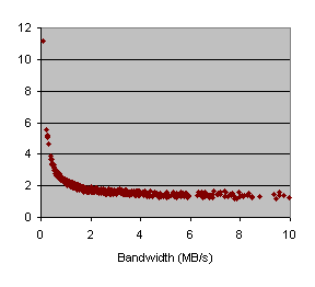
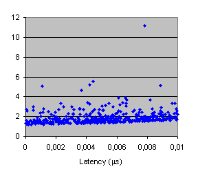
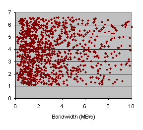
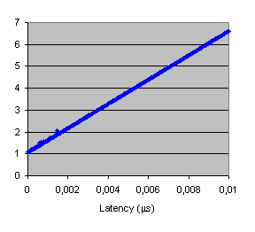
This last example analyzes the influence of latency and bandwidth in two different applications, while the reaming parameters of Dimemas remain unchanged. This analysis has been performed mixing the execution of Dimemas and ST-ORM, where we start up to 1000 shots (Dimemas simulations) with different parameters. Figures 47 show the results for the FFT application, and Figures 48 show the results for PDE.
|
|
|
|
|
|
We have also performed the Spearman analysis to get a measured value of the most influent paramter for each application. Figures 49 show that FFT is clearly influenced by bandwidth, but PDE has latency as the most important parameter for the application time.
|
|
|
